Wemos D1 Mini Pinout and Specs
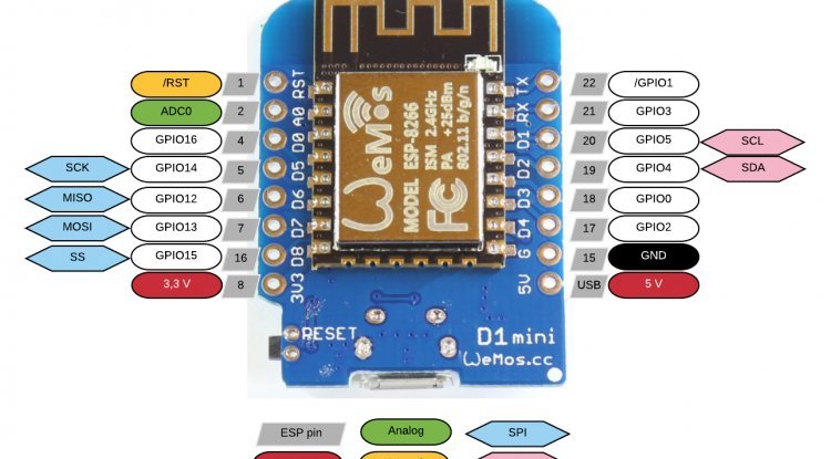
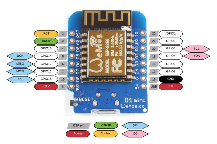
The following table shows the correspondence between the labels on the silkscreen and the GPIO number as well as what pins are the best to use in your projects, and which ones you need to be cautious.

| Label | GPIO | Input | Output | Notes |
| D0 | GPIO16 | no interrupt | no PWM or I2C support | HIGH at boot used to wake up from deep sleep |
| D1 | GPIO5 | OK | OK | often used as SCL (I2C) |
| D2 | GPIO4 | OK | OK | often used as SDA (I2C) |
| D3 | GPIO0 | pulled up | OK | connected to FLASH button, boot fails if pulled LOW |
| D4 | GPIO2 | pulled up | OK | HIGH at boot connected to on-board LED, boot fails if pulled LOW |
| D5 | GPIO14 | OK | OK | SPI (SCLK) |
| D6 | GPIO12 | OK | OK | SPI (MISO) |
| D7 | GPIO13 | OK | OK | SPI (MOSI) |
| D8 | GPIO15 | pulled to GND | OK | SPI (CS) Boot fails if pulled HIGH |
| RX | GPIO3 | OK | RX pin | HIGH at boot |
| TX | GPIO1 | TX pin | OK | HIGH at boot debug output at boot, boot fails if pulled LOW |
| A0 | ADC0 | Analog Input | X |


